Design Your Own PiMICS
While there are downloadable files you can find on this page, ideally, you will design your own PiMICS. It will be much more satisfying and enhance your creativity. It will help you develop the skills to build other things in the future. 3D modeling and printing are marvelous technologies that every scientist and engineer should learn. Don’t skip this learning opportunity.
The creation process: Give some thought of what you would like to study after you have built your camera. Watch some YouTube videos about what people do with hyperspectral or multispectral imaging. Read some papers and see what others have done. Go to Google Scholar and type in “Applications of hyperspectral imaging” or “Applications of multispectral imaging”. Then, using a 3D modeling software program design your new camera. Personally, I really like using Blender. It is a free open-source 3D modeling and animation suite. There are a host of really good introductory videos online. After roughly 10-15 hours of practice, you will have a sufficient level of competency in 3D modeling. There are other excellent packages that are quicker to learn like Tinkercad or Fusion360, which are also free for personal use. You will then create a 3D printable file like *.stl that you can import, slice and print on a 3D printing platform.
3D Printing and Soldering
It is assumed that you will be able to 3D print the body of the camera and have access to basic soldering tools (soldering iron, helping hands, flux). If you don’t have access to a 3D printer, I highly recommend Prusa printers. They are workhorses and reliable. I did quite a bit of study about which 3D printers to buy. I used to have Lulzbot Taz 6, but they stopped making those and the Prusa printers are much cheaper, easier to use and more reliable. I am a huge fan of the Prusa MK4S, but the Mini is also excellent and costs around $460 semi-assembled (I assembled my first one by the full kit. That takes awhile, some patience and a realization that you are probably going to make some mistakes). Prusaslicer is a simple-to-use slicing program that will take your .stl file and create a printable gcode or bgcode file.
You will also need a basic soldering kit, which should include a soldering iron, solder, and “helping hands” (yes that is its name, a little metal body with clips to hold your wires. There are many types of helping hands that are really annoying to use or wear out quickly (personal experience here). My recommendation for helping hands from Pro’s Kit and can be find here. By the way, I have no financial incentives from any of my recommendations. These are just based on experience.
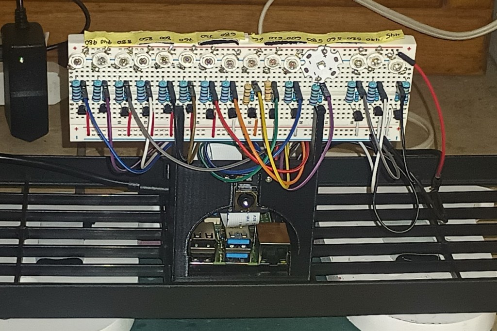
Camera 1: PiMICS Basic
This is the model shown in the figure above. The stereolithographic file (.stl) for 3D printing PiMICS Basic and some basic Python code can be found at GitHub. You will be able to find other 3D printer files as well as Python code links in the People and Projects section. PiMICS Basic is our simplest model to build. It can take anywhere from 2 hours to 20 hours to build depending on your skill level. We will post an instructional video on this camera. If you want to post your video and send us the link, we can do that as well. Here is a recommended list of items:
- Raspberry Pi 4b, SD card with Raspian, 5V power supply (One complete package option is the Raspberry Pi 4 Complete Starter Kit- Includes Raspberry Pi 4 Board, Fan Cooled Case, 64GB Preloaded Micro SD Card and More (4GB, , but it has stuff you won’t need)
- Monitor (any HDMI-enabled monitor will work). You can even use a small monitor that physically holds the Raspberry Pi on back like “7’’ Raspberry Pi Screen, IPS1024×600,Responsive Smooth Touch,Dual Built-in Speakers,HDMI Input,Compatible with Raspberry Pi 5/4/3,Driver Free“. Although, it can be harder to code with a small monitor, but it is nice if you want to make the system portable. I actually recommend writing using both monitor outputs, one for your coding(large) and one to make it portable (small 4, 5 or 7 inches).
- Solderless breadboard. One option is 4PCS Breadboards Kit Include 2PCS 830 Point 2PCS 400 Point Solderless Breadboards for Proto Shield Distribution Connecting Blocks
- Cables for Pi to breadboard. We like the “ELEGOO 120pcs Multicolored Dupont Wire 40pin Male to Female, 40pin Male to Male, 40pin Female to Female Breadboard Jumper Ribbon Cables Kit Compatible with Arduino Projects“
- npn transistors. Any generic npn transistor will work we used the “BOJACK 2N2222 NPN 60V 0.8A 0.5W 250MHZ Power General Purpose Transistors(Pack of 200 Pcs)
- Jumper wires kit. We used 840Pcs Breadboard Jumper Wire kit for Arduino, 14 Vaules, 2 mm/0.08″-125 mm/4.92″ Minidodoca U-Shape Magnetic Jumper Wires Assortment kit & 4Pcs 34cm/13.4 inch Length
- Camera. We recommend the camera module 3 NoIR. It is important to get the NoIR version, because the infrared (IR) filter is removed. You can use a regular camera module 3, but you will need to remove the filter anyways. There are Youtube videos about how to do so. We bought ours from Sparkfun.
PiMICS Basic Parts List Part 2: The harder part
The previous components work broadly. We highly recommend that you read the paper Raspberry Pi multispectral imaging camera system (PiMICS): a low-cost, skills-based physics educational tool in the “Publications” section, especially about the resistors the electronics portion of the experiment. That will give you an understanding of how to choose your resistors. If you want to simply copy what we did, that is fine (posted below), but you may want to think about this a little more deeply depending on your application. In the publications section of this website, you can read about some fundamentals associated with electronics. For example, if you want to make a portable camera that runs on batteries only, you could have a 5V power bank with two output ports, one for the Pi and one for the LEDs, that would be easy to do. We recommend the Anker Zolo 10,000 mAhr powerbank. You will want to match power requirements of your LEDs with with power supplies and resistors. Once you have decided on your LEDs and illumination power, you can then choose your power supply and resistors.
Choosing LEDs
This was the most difficult part of this project. Digikey has thousands of different LEDs at many different wavelengths. But, before purchasing, you should consider your application. What do you want to do? How much power do you want to use? How important is the uniformity of your illumination? This part I leave more up to you with some pointers. I found 19 LEDs that spanned 400 nm to 970 nm in 5mm packages on Amazon and Digikey. For example Bojack sells a 10-color (20 LEDs of each color) LED set at visible wavelengths for about $10. Only 7 of those 10 colors can be used as narrowband sources. The other wavelengths in the infrared, I found on Digikey. I didn’t particularly like the 5mm packaged LEDs, though, because they didn’t have uniform illumination, which ishelpful when you are trying to get accurate reflectance readings. You can compensate this by calibrating your imaging system in code, but you need to be moderately good at coding in Python to do this.
CAUTION: The following LEDs I am going to propose that you use are very bright. I run them far below their maximum power and I don’t look at them directly. Exercise good judgment and watch some safety videos about how to use bright LEDs. I preferred using the 3W chip LEDs from vendors I found on Amazon, namely Chanzon and Topxcdz. You need to scroll through their options and make sure you get the 3W. They have a range of colors spanning 450 nm to 980 nm. The unfortunate part is that they only sell them in quantities of 10 or 50, which is great if want to build 10 or 50 working models, but not so great if you are working alone.
I am working with Sparkfun to make a one-stop shop for all of this equipment including the high-powered LEDs.
The other equipment
- 6V power supply for the LEDs (we stripped the leads and soldered jumper wires to connect it to the breadboard)
- Resistors (22 Ohm 1Watt AND 1kilo Ohm 1/4 Watt). These resistors were used for the 3W LED chips. If you want to do low power LEDs, I recommend (300 Ohm 1/4 Watt and 1 kilo Ohm) You will need at least 15 of each, but you should buy extras. I usually buy these in packs of 100. See the paper in the Publications section for more information.
- We purchased Chanzon and Topxcdz 3W chip LEDs of wavelengths in nm (445, 490, 530, 590, 600, 620, 660, 680, 760, 800, 850, 880, 940, 980). There are also 560 and 730, but the 560 is different package type and we found the 730 to be the wrong color from several vendors (actually 760). Hopefully, that will be fixed soon. You can see the 560 nm LED in the image above.
Camera 2: PiMICS Zero
Zero will require quite a bit more time, because you will need to do a lot more soldering (about 200 solders). Instead of the solderless breadboard, we used the Electrocookie Prototype PCB Solderable Breadboard for Electronics Projects Compatible for DIY Arduino Soldering Projects, Gold-Plated (5 Pack + 1 Mini Board, Matte Black). This uses the same configurations as in PiMICS Basic (shown at the top of the page), except that all the electronics minus the LEDs can go on the back of the breadboard (basically, look at PiMICS basic and imagine all of the electronics, except for the LEDs on the back of the breadboard). This allows you to put the LEDs right next to the face of a printed camera as shown in the figure below. You can see the small screw up above the LEDs that is holding the breadboard to the camera. It gives your camera a much more aesthetic look and is more robust. Another possibility is to solder wires to all of the LEDs and then glue the LEDs in a desired location, like a circle around your camera.
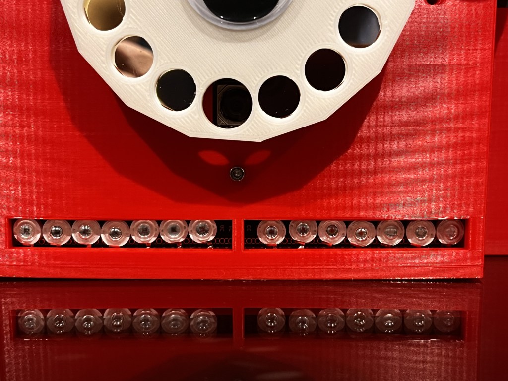
To compete PiMICS Zero, you will need color or bandpass filters. That is a work in progress. See the next section. They are 10 mm x 10 mm filters placed in a 3D printed filter wheel.
Chroma Technology Filters
Normally, Chroma Technology filters cost about $360/filter. So, buying 15 filters will cost you over $5000. They are high quality narrowband interference filters. However, we are trying to raise sufficient money to fabricate hundreds or thousands of these at a time. If we can do that, we can get the price down to about $10/filter. This would allow you to do passive multispectral, which enables a whole range of powerful imaging capabilities. We need to raise about a quarter million dollars to do this. Please consider donating to help us make this a possibility. We have explored other possibilities as well. We will continue to look for inexpensive solutions to make this a possibility. One crazy idea we are exploring is using powerful digital signal processing techniques like compressive sensing on extremely low-cost plastic color filters to achieve high resolution spectral reconstructions.
